2011年12月18日 星期日

AXIS M1011-W相機與NI Vision實測

發現了一款很好用的相機!

NI 的Vision Acquisition (NI-IMAQdx)除了可以支援USB,GigE,還有IEEE 1394的相機,他還可以支援某些廠商的IP Camera (主要是以Basler和AXIS這兩個廠商的IP Camera為主。) 既然可以用網路連到相機,那為何不能用無線網路連到相機呢?

於是最近敗了一個AXIS M1011-W來玩一玩。幾張開箱照:

IMG_1608

IMG_1609

裡面沒什麼,就相機跟5V的power supply。

IMG_1610

後面: 若沒有無線網路還是可以用有線來跟他連,這點蠻不錯。

IMG_1611

先找個地方擺吧! 要接的線只有電源線一條。

Setup很簡單,只要讓他連上無線的區域網路,電腦就可以從它擷取畫面。MAX也可以抓的到。

image

一旦MAX抓得到,當然之前用的Vision程式也都可以繼續用。

image

假如機器人上直接有5V的電源供應,這個相機就可以直接吃機器人的電,然後PC就可以透過無線網路來抓到機器人的影像了!

-John

2011年7月29日 星期五

Microsoft Kinect for Windows SDK Beta available for download

image

(Saying hi from our messy office …)

Unforunately I won’t be making it to NIWeek this year, but I’m curious as to what they’ll be presenting at the Robotics Summit.  One of the sessions will be talking about hacking the Xbox Kinect (which Ryan Gordan has done already, mentioned from my previous post.)  However, I haven’t had time to play around with the OpenKinect DLLs to get skeletal data showing in LabVIEW, I think that really would be the ultimate goal.

Word has it that Microsoft has released their own SDK, this might prove easier to integrate than some of the open-source stuff (hopefully.)  Let’s see if we can get a tune out of this trumpet.  Stay tuned …

-John

Skeleton tracking image

2011年4月12日 星期二

利用LabVIEW擷取編碼器的資料(encoder)

最近剛好幫一個客戶做驗證,順便po上來跟大家分享。一般馬達通常都會有個編碼器(encoder)來量馬達的位置還有轉速(若不懂編碼器是什麼,請看這邊: 編碼器原理概論。) 要是馬達沒有編碼器的話,那我們也可以再額外加裝上去。台灣目前最常看到的兩家encoder廠商有企誠(www.honestsensor.com.tw)還有鴻璿(www.encoder.com.tw, 很好記吧),在他們網頁上會有很多各式各樣的encoder.

最近跟企誠買了一款encoder,決定用NI DAQ先給它測一下。因為NI DAQ的DIO還有counter都是5V TTL準位,所以挑選encoder的時候也記得要確認這個spec。另外也要看encoder本身需要的電源是幾伏特,這一款剛好是5V,所以可以直接拿DAQ上的5V輸出來供電給encoder。我用了一款NI USB-6212,蠻方便的。

Encoder連到DAQ示意圖:IMG_1182

接線很簡單: 紅(5V),黑(GND),綠和白為AB相位,分別接PFI0,PFI9 (這兩條是DAQ CTR0的input,我們就是要用counter來幫我們計數encoder的方波)IMG_1183

若是用LabVIEW的話,可以直接開一個現成DAQ的範例﹕Measure Angular Position.vi

IMG_1184

之後用手把encoder動一動,LabVIEW就會量到現在目前的角度啦! 

要用CompactRIO來做的話也是一樣,記得要用Digital Input或是DIO的模組(例如9411,9401),Scan Mode裡面可以直接選擇encoder輸入,把線接好相對應的接腳就可以了。

-John

2011年4月5日 星期二

Using an Bluetooth to RS-232 Converter for Robotics Use

Not much of an update this week, but we found something that can be really useful to us roboticists.  RS-232 is still a pretty standard interface among sensors for robotics.  In fact, much of the instrument drivers included in the LabVIEW Robotics Module are for RS-232 sensors (Hokuyo, Crossbow IMU, Garmin GPS etc.)  Well, what if you didn’t want to tether your sensor to your PC or CompactRIO?  Much like how you can replace ethernet with wifi, you can also replace tethered RS-232 with an off-the-shelf Bluetooth-RS232 converter.  Here’s a short video of us using this in a Hokuyo LIDAR setup.

If you are in the US, you can grab one of these converters off of sparkfun.com:

Bluetooth Modem - Roving Networks RS232

Once your bluetooth-equipped PC scans and finds this device, your PC adds an additional COM port to your device manager.  Run your RS-232 programs as before, and you will now have a wireless link to your RS-232 device.

A few things to note:

1. You can manipulate the Bluetooth converter to run at your specified baud rate.  Remember, the baud rate of the sensor, the BT converter, and the BT COM port on your PC all have to be the same.  However, we did notice slower data transfer, even at the same baud rate (running a Hokuyo LIDAR at 115.2kbps.)  Just like how wifi doesn’t actually achieve transfer speeds like regular ethernet, this BT converter will have an effect on your transfer speed as well.

2. This Sparkfun unit has a RS-232 driver built in, so you don’t need to add another voltage converter for RS-232.  See this tutorial to learn why you need a driver/voltage converter.

Seattle Robotics, Project: RS-232 to TTL cable

As always, keep your feedback coming!

-John

2011年3月31日 星期四

Using LabVIEW to acquire iPhone accelerometer data

Here’s another oldie but goodie … sometime last year I wrote code to acquire iPhone accelerometer data.  It’s the same concept as using LabVIEW to acquire Wii accelerometer data, but a little simpler since all you need is to get your PC connected to your iPhone via wifi.  You also need an app such as Accel Pro or iSensor, these apps can stream and broadcast your iPhone accelermeter data through UDP protocol.  I personally recommend Accel Pro over iSensor, the newest version of iSensor (1.01) has a bug that disable the Z axis values, but hey, you can’t really expect maintenance for a free app.  Although Accel Pro is $4.99, it’s got some more functionality than iSensor such as filtering and datalogging, so it’s worth taking a look.  However, Accel Pro doesn’t include compass data like iSensor, that’s a shame.

*Caution: Some apps may claim the ability to stream UDP data, but you might have to take a look at the UDP packet protocol for the app.  Just so happens that these 2 apps have almost the same protocol, for example:

ACC: 376153408593b159a8b5f0b75b29d642694394c0,173429.723,-0.091,-0.743,-0.634

So everything before the first comma is pretty much garbage, the second number appears to be a clock or a counter of some sort, and then comes the X, Y, Z, and compass data.

Be sure to switch broadcast mode on your iPhone app from “broadcast” to “unicast”, this seems to give the best performance.  You can download the LabVIEW 2009 code from below (right click on the link, then click “save as”.)  The code is just a variation of a LabVIEW UDP shipping example.  Enjoy!

[image[17].png]

http://groups.google.com.tw/group/riobotics/web/UDP%20Receiver%20for%20iSensor%20app.vi

-John

2011年3月5日 星期六

LabVIEW, Xbox Kinect, and 3D point cloud visualization

ttt

Lately there has been alot of buzz about the Microsoft Kinect accessory, especially within the area of mobile robotics.  Imagine, a 3D scanner for not 2000 USD, but 200 USD!  Well, if you already happen to use LabVIEW, things just got a little easier.

This post is actually a response to the great work that Ryan Gordan has been doing over at his blog, http://ryangordon.net/.  Ryan’s already put up a LabVIEW wrapper for the OpenKinect library … if he had not done this, my experimentation would not have been possible.  So, kudos to Ryan.

You can get started pretty fast using Ryan’s LabVIEW example – grabbing the RGB image, 11-bit depth image, and accelerometer data off of the kinect.  I know that other people have gone on to using the kinect for 3D scene reconstruction (i.e. MIT), I was just curious if LabVIEW could do the same.  So, after some google searching, I found a LabVIEW point cloud example and combined that with Ryan’s example code.  Here’s how to get started:

1. Get your kinect connection up and running first.  Ryan has included inf files on his site, I have as well in my download link.  Be sure to install Microsoft Visual C++ 2010 Redistributable Package.  Check http://openkinect.org/wiki/Getting_Started for more information.

2. Run Ryan’s example.vi first to get a feel of how the program works.  It’s the typical, but very handy, open –> R/W –> close paradigm.

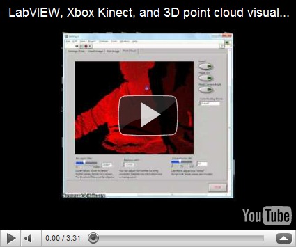
3. Now open up Kinect Point Cloud.vi.  The tabs on the top still have your depth image and RGB image, but now I’ve added a point cloud tab.

image

image

ttt

4. There are some options that you can adjust while in the point cloud tab.  There is a filter that lets you remove far objects, you can adjust the threshold on the lower left.  “Invert” is to turn the 3D inside out, pause 3D holds the current 3D view, and in case you lose the mesh while scrolling around in the 3D view, use the reset camera angle button.  BTW, use your left mouse button to rotate the 3D view, hold down shift to zoom in/out, and hold down ctrl to pan.

5. If you choose color binding mode to be “per vertex”, something interesting happens:

image

You can map the RGB values to the 3D mesh!  Obviously there is some calibration needed to remove the “shadow” of the depth image, but that’s something to fiddle with in the future.

6. For those of you who care, I’ve modified Ryan’s “get RGB image” VI and “get depth image” VI so that they output raw data as well.  Just wanted to clarify if case your subVIs don’t match up.

The idea behind displaying the 3D mesh is pretty simple, it’s alot like the pin art toy you see in Walmart:

The kinect already gives you the z-values for the 640x480 image area, the LabVIEW program just plots the mesh out, point by point.  I had wanted to use the 3D Surface or 3D Mesh ActiveX controls in LabVIEW, but they were just too slow for real-time updates.  Here is my code in LabVIEW 8.6, I’ve bundled Ryan’s files with mine so you don’t have to download from two different places.  Enjoy!

Download: LabVIEW Kinect point cloud demo

Things to work on:

I am a bit obsessive about the performance of my LabVIEW code.  For those of you who noticed, the 3D display will update slower if you choose “per vertex” for color binding.  This is because I have to comb through each of the 307,200 RGB values that was already in a 3-element cluster and make it into a 4-element RGBA cluster so that the 3D SetMeshParms node can take the input with an alpha channel.  If any of you know how to do this in a more efficient way, please let me know!  This really irks me, knowing that I’m slowing down just to add a constant to an existing cluster.image

I have also seen other 3D maps where depth is also indicated by a color gradient, like here.  I guess it wouldn’t be hard to modify my code, it’s just some interpolation of color to the depth value.  But that’s a little tedious to code, I prefer spending more of my time playing with 3D models of myself!  (Uh, that sounded weird.  But you know what I mean.)

A little about me:

My name is John Wu, I’ve worked at National Instruments Taiwan for about six years, now I’m at a LabVIEW consulting company called Riobotics, where we develop robots with LabVIEW not only for fun, but also for a living!  Please leave your comments and feedback, I’d love to hear from you.

-John

2011年1月25日 星期二

會馬殺雞的機器人─WheeMe


文章來源:Yahoo!奇摩 發表時間:2010/12/03

會馬殺雞的機器人─WheeMe

當你倒臥在沙發上看電視、或趴在軟墊上聽音樂時,如果有人貼心地幫你按摩一下,那肯定是種無上的享受。當然,如果有人願意做這件事,那是再好不過了;假如眼前沒有這樣的志願者,別擔心,就讓機器人來幫你按摩一下吧!

WheeMe是個會讓你通體舒暢的機器人

別以為這時候會走出一個巨大的人形機器來虐待你,畢竟如同某手機大廠的名言:科技始終來自於人性。由DreamBots公司所推出的WheeMe,是個手掌般大小、有如可愛小瓢蟲一般的機器人,它能在你的背上或腹部四處遊走,以十分溫柔與緩慢的速度,很有耐心地按摩它所經過的每一個地方;在為你服務的時候,WheeMe會十分地安靜,而且你也不必擔心它會摔落到地面,因為在斜度過大的地方,它會自己倒退回安全處。

三顆3號電池就可以驅動WheeMe

或許你會以為,WheeMe是以自身的重量來產生按壓的效果;其實WheeMe並不重,只有300多克而已。它之所以能夠讓你通體舒暢,主要是它會產生震動,並透過輪子上的薄片施壓,產生按摩的作用。官方表示,WheeMe適用於身體上有著大塊平面的部分,像是你的背部或是腹部等位置。WheeMe的動力是來自於三顆3號電池,因此沒有電線等惱人的束縛。而這玩意兒也不需要搖控器,因為它會隨機性地四處遊走,因此並不需要另一個人協助操作。而且保養的方式也很簡單,只要用乾布清潔一下輪子就可以了。

不需要別人幫忙,WheeMe就能幫你按摩

在官網釋出的見證影片中,每個試用者都笑開懷;雖然我們難以體會實際的效果,不過這樣的按摩機器人還是蠻討喜的。心動嗎?明年初就會正式開賣了唷~

圖片來源:DreamBots公司官網

2011年1月19日 星期三

Visual Servoing: 利用LabVIEW進行影像軌道追蹤


天啊,沒想到時間過得真快,一下子就跨到2011年來,John真的是很慚愧,好像最近blog都沒有在update,不過為了幫各位準備很棒的內容,我還是希望能夠秉持先求質,再求量的原則。這次為大家準備的是我最近在研究的機器人影像處理專題,希望對大家有所幫助。

我們都知道,網路上已經有很多有關循跡機器人(Line-following robot)的範例,大部份其實都是用LEGO NXT和光感應器來做循跡的動作。原理很簡單,假設地上貼了一條黑色膠帶,當往地面指的光感應器經過了這條黑線,光感應器就會回傳不同的反應值,由此機器人就可以判斷左右行走的策略。一般的程式應該會有像這樣的邏輯:

while

if (lightsensor <= threshold)

turn left

else

turn right

當然,只用光感應器會有一些限制…光感應器的感測距離沒有很遠,接收器離地面的距離通常要在5cm以內才能擷取到有意義的反應。換言之,機器人必須已經接近軌道才能去追隨它。假設機器人離軌道還有一段距離,那這該怎麼辦呢?

理想中,如果我們有個相機能夠往前方拍攝,這樣機器人說不定就能夠「預測」軌道的位置,如果機器人離軌道還有一段距離,它就可以自主搜尋軌道方向並往其方向前進。(*為達到這目的當然還有很多其它做法,不過以這次的分享我們先以影像來探討解決方案。)

用相機來拍聽起來很簡單,但是整個演算法計算過程其實是有很多要考量的。我們可以先把這問題先簡化 … 在之前的文章我有分享過用LabVIEW做影像物件追蹤 (ex 1 2。) 基本概念是,如果可以取得物件的X座標,那麼我們可以拿這座標和畫面的中心點做比對,例如一張640x480的畫面的橫軸中心點為320 (因為640/2=320),如果物件的X座標是400,那機器人應該要往右轉,若座標為200,那就應該要左轉,這時候機器人的行為就會像之前的LEGO NXT循跡機器人,它會隨著物件的相對位置來調整它的行走方向。

如果我們要追蹤的是一條線而不是一個單一物件,我們必須要先對畫面做些前處理。在之前的物件範例,我們把物件的位置收斂成畫面上的一個單一中心點。以線來講的話,我們可以抓這條線與畫面下方的交叉點為機器人的行走方向。為增加此範例的複雜度,我們乾脆用兩條平行的線來做示範。

在這兒先給各位看我是如何從彩色畫面中抓到線與畫面下方的交叉點位置。首先這是原始畫面(我在書房地板上貼了兩條平行的白膠帶):

original

1. 先進行色彩HSL二值化,將白色的物件先獨立出來。二值化的參數則是可以從Vision Assistant的互動式界面來調的。若不了解怎麼調參數,請參考這篇文章: http://riobotics.blogspot.com/2009/06/hsl.html

 threshold

2. 畫面中難免會有一些其它相同顏色的物件,這時候再用個Convex Hull函式,把小物件和雜訊添滿。

morphology

3. 看起來我們的「線」和其它的物件有個很明顯的差異,「線」看起來都是細細長長的,只要不是「線」的物件都看起來圓圓肥肥的。NI Vision的particle filter函式裡面有個篩選條件叫做elongation factor,意思是說,越細越長的物件,它的elongation factor的分數會越高。我們可以用particle filter把elongation分數較低的物件濾掉。

particle filter 1

4. 嗯,看起來偶爾還是會有漏網之魚。左邊多出來的物件應該可以靠它的高度(Height)把它濾掉,也是一樣用particle filter。

particle filter 2

5. 呼,畫面經過了一番處理,終於只剩下我們需要的兩條線了。我們可以再用Particle Analysis的Max Feret Diameter Start和Max Feret Diameter End把線的兩端X,Y回傳回來。如果需要的話,可以再加一個Bisecting Line含式來計算兩條線之間的中心線。再加一些overlay的含式,就可以把這些資料重疊在畫面上。現在所回傳的三個數據是線與畫面下方邊緣交叉的X座標。

image

現在是還沒有時間把這個演算法套在一個實際車體上來測試,不過近期之內應該會完成,到時候會拍幾個影片給大家參考。基本上,只要把中心線的X座標鎖定在畫面的中心320,車體就會隨著軌道的方向進行了。

軌跡追蹤 Vision Assistant 範例.zip

軌跡追蹤 LabVIEW 範例.zip

(這個LabVIEW的檔案會比較大,差不多80MB,因為我有附了一些測試的AVI影片)

-John

(4/14/2011 更新:)

以上演算法實際上到底跑起來效果如何呢? 我們在一個小型的機器人平臺上 Easy Robot來驗證演算法這個演算法的實用性。我們先用一條線來代表軌跡。在影片裡,請注意當機器人尋找軌跡時,後面的惰輪幾乎是完全壓在線上的,代表此機器人的準確度。

嗯,測試結果比想像中的還好。可以出貨了!

-John