顯示具有 NTU Project 標籤的文章。 顯示所有文章

2009年6月24日 星期三

大成功: CompactRIO 機器人自走車展示!

終於到了學期末了,努力了一學期,昨晚剛好是我們的成果發表會,在此和大家分享一下。 雖然說學員們真正能夠做這個 project 的時間才差不多一個月半,但是他們的成就真的是讓人刮目相看 … 真是對的人遇上了對的工具。

需要復習一下 project 規則嗎? 請看這兒:

http://riobotics.blogspot.com/2009/06/unmanned-guided-vehicle.html

首先,各組先做簡報,來分享他們解決這次問題的方法與挑戰:

士強 1

(帥啊,士強!)

做完簡報之後,就到了實際上戰場的時候啦! 各隊這時候就趕緊做最後的參數調整。

Practicing 2 Practicing 1

這裡是最成功的一組的成果,perfect run!

為感謝這次學員的努力,NI也派工程師來和老師一起頒發榮譽獎狀。

certificate

CompactRIO,YA!

group 1

雖然是demo完了,但還是對 CompactRIO 機器人依依不捨,再拍張照吧!

Robot 1

做完問卷調查之後,發現學員們的反應有幾個共同點:

1. 透過這次課程還有project,有讓大家更了解機器人系統整合的概念! 之前大家或許是有寫過視覺演算法或摸過一些馬達,但是很少能夠有機會能夠體驗整個系統是可以如何整合在一起的。

2. LabVIEW是個容易上手的程式語言,但是程式變的比較複雜的時候,圖形化的debugging方式還有trace會變得比較吃力。

3. 硬體週邊(馬達,感測器,camera)需要更完整整合,希望可以提供其全的配備,以及設定上的說明。

我想,下次這個課程開的時候,應該可以有更多時間可以講一些LabVIEW的中級概念,好讓學員能夠有效率的維護程式並進行除錯,不然一頭栽進LabVIEW的話,很容易會被自己拉的像蜘蛛網般的線絆住。另外,之後也會提供更完整的 robot kit,讓學員可以很快的從這個平臺上手。

I would like to thank all of the students for their hard work and motivation.  Without your passion in robotics, this class would not be successful.  Keep up the good work!

2009年6月14日 星期日

HSL 色彩空間原理


各位還記得上次我們在用 AXIS 206 測試的時候,我們用了一個神奇的視覺程式,先讓 camera 校準了一下,然後它就可以抓顏色了嗎?  在此解釋一下它的運作原理: HSL 色彩空間 (Hue, Saturation, Luminance.)

在這之前,我們先回顧一下,平常我們比較用 RGB 的色彩空間來描述一個圖片或畫面。電視,LCD螢幕,投影機都有用到RGB。不熟悉 RGB 原理的朋友們可以從這邊來復習一下:

維基百科: 三原色光模式

Wikipedia: RGB color model

用在於一些基本的顏色辨識應用上,RGB 通常是夠用的,因為你只要設定你要抓的R值,G值,還有B值範圍,基本上那個顏色區塊是可以被你隔離出來的。從下面的圖片我們可以看得到,這張圖片要是用RGB的 histogram 來看的話 (左下角),RGB各個區域有三根”刺”,這其實是因為在圖片裡灰色檔案櫃佔圖片面積居多,而灰色剛好又是RGB三色合成的。

image

我們把那三個刺隔離出來給大家看一下,有沒有發現被隔離出來的區域大部份都是櫃子?

image

當然,因為打光的關係,櫃子的某些部份是沒有被抓到的。在RGB色彩空間下做色彩辨識,很容易會被不平均的光源影響 (比較沒有打到光的部份,根本就已經幾乎是另外一種灰色了…

再試試看抓綠色燈罩的部份:

image

因為打光的關係,燈罩的右側反而是比較亮的。我們只能做個取捨,抓左側面積比較大的,比較暗的綠色。如果硬要亮暗綠色統統抓的話,那可能結果就會像這樣:

image

可憐啊,看來背景的一些”綠色”的東西也被抓進去了…

如果我們可以用另外一個方式,將亮度的影響降低,那或許效果會比較好一點。於是,現在就會用到HSL了。

HSL stands for HUE, SATURATION, and LUMINANCE color space that corresponds to projecting standard RGB color space. HSL separates out HUE from SATURATION and from brightness. Thus, the problem of luminance variation can be solved in this case since the LUMINANCE plane has been separated out.

因為HSL將亮度放在另外一個平面,而不是像RGB讓它跟顏色混在一起,看起來抓顏色應該會容易許多。重點是,當光源環境一直在改時(例如,機器人跑來跑去),追蹤能力會穩定許多! 請看以下:

image

以上都是用 NI Vision Assistant 的 Color Threshold 函式來完成,函式可以直接支援RGB或HSL色彩空間。

2009年6月8日 星期一

機器人障礙迴避 - 實作影片


不好意思,手機拍的影片很爛,我會找時間再拍個比較好的影片,不過先給大家看一下用 URG 的實作範例。現在機器人是完全自主在跑哦!

Calculating the angle of the nearest obstacle from the Hokuyo rangefinder

Now that you can obtain the range magnitude and angle arrays from the Hokuyo LabVIEW VI, here’s a little subVI to help identify where the nearest obstacle is.  Keep in mind, 0 degrees is straight ahead, positive angles are towards the left side of the sensor, and negative angles are towards the right side of the sensor.  You can add it to the Hokuyo VI like this:

image LIDAR Max and Min.vi

2009年6月7日 星期日

AXIS 206 Camera 測試


這個週末剛好想要測試一下這個AXIS 206相機到底可以辨識顏色到什麼程度,哇真頭痛,該拿什麼道具來測呢? 突然靈機一動,想到家裡有些IKEA的臺燈,剛好可以派上用場,於是禮拜六就殺去了IKEA多買了幾個燈罩,然後再整合了一些之前寫的LabVIEW範例程式。

SKIMRA Shade

現在可以做到的是,Red Green Blue都可以正確辨識,當然事先要先讓程式calibrate一下,它才能知道顏色的HSL參數範圍在哪兒。不懂HSL原理沒關係,我之後會再po一些相關資料。重點是,我們已經可以抓到顏色以及它佔的大小,甚至這個物件的輪廓和中心點 (哈,中心點之後會再加進去LabVIEW程式裡,不過大致上不會很難。)

Red:

image

Green:

image

Blue:

image

請下載這個壓縮檔,然後開“LocateColoredObjectExample_AXIS.vi” 試試看。先選擇你要鎖定的顏色 (red, green, or blue),然後再按一下”Calibrate” 按鈕,你就可以用這個程式做物件追蹤了。

LocateColoredObjectExample_AXIS.rar

2009年6月4日 星期四

Interfacing to the AXIS 206 Camera (part III)

既然我們已經從PC上跟Axis Camera連線成功了,現在我們可以試著將AXIS 206連到 cRIO-9074 的第二個網路孔 (記得哦,是第二個,第一個孔是讓 CompactRIO 接到電腦的。)

首先我們先來做些設定。從MAX裡找出你的CompactRIO,選擇 “Advanced Ethernet Settings”選項。

image

在左邊選擇第二個 ethernet port 的 MAC address,然後將 mode 從 “Disabled” 調成 “TCP/IP Network”. IP address 可以設成跟你 AXIS 206 的 IP 地址同樣 subnet。按ok之後,CompactRIO會需要重新開機。

image

接下來,我們就可以用之前 Part I 的程式來從 cRIO 跟 AXIS 206 Camera 溝通了!  Remember to move the VI from the “My Computer” level in the LabVIEW Project to the cRIO level in the LabVIEW Project.

 image

2009年6月3日 星期三

Interfacing to the AXIS 206 Camera (part II)


注意嘍,CompactRIO 的原廠設定是不支援 NI Vision 函數的,不過我們可以 Hack 一下 CompactRIO 來克服這個問題。

There are two install scripts located under these locations:

C:\Program Files\National Instruments\RT Images\Vision\8.6.0\install.cdf

C:\Program Files\National Instruments\RT Images\CommonVision\nivissvc.cdf

Replace with these files:

CDF files to replace

Note: These CDF files are for LabVIEW 8.6.0 only.

Once the scripts have been correctly updated, relaunch MAX and download Vision to your cRIO target.  Right click on Software and select Add/Remove Software.

image

Select Custom Software Installation.

image

Highlight NI Vision RT and select “Install the feature.” Click Next. 

image

Reboot and you’re done!

Interfacing to the AXIS 206 Camera (Part I)


The AXIS 206 is an ethernet-based camera that supports up to 640x480 resolution.  The camera has a built-in web server that allows you to monitor the live images from a web browser.  Just type in http://x.x.x.x where x.x.x.x is the IP address of your camera.

The camera might ask you for a user name and password when you connect to the page, usually the user name is “root” and the password is “pass.”  Find the option in the settings menu to switch on “anonymous login” so that this prompt won’t show anymore.  This way we can use a program from LabVIEW to control the camera without being blocked by the password.

The VI you want to run is called “axis_03_grab.vi”.  You’ll need to also have the NI Vision Development Module installed before you run it.

Don’t run this VI on the CompactRIO yet, because I haven’t told you how to modify the CompactRIO so that it can run the vision algorithms.  You can run this VI on the PC first to experiment with it.  Remember to change to IP address so that it matches your camera!  When connecting from a PC without a hub or router, make sure to use a crossover cable, otherwise you might have some problems.

image

AXIS 206 Vision VIs download

Also, if you have trouble finding CalculateFPS.vi, here it is for download.

CalculateFPS.vi download

CompactRIO Scan Mode Tutorials

Here are some tutorials from the NI website to show you how to use CompactRIO Scan Mode.  You’ll probably want to use Scan Mode to output an analog voltage from the NI 9263 analog output module to control your motors.

English tutorials

Chinese Tutorials

2009年6月2日 星期二

LabVIEW 連到 Hokuyo URG-04LX 雷射測距儀

還蠻簡單的,just follow the instructions below:

1. Download the Hokuyo URG-04LX instrument driver from ni.com/idnet (search for Hokuyo.)

http://www.ni.com/devzone/idnet/

2. Install under Program Files\National Instruments\Labview X.X\instr.lib

3. Plug in the USB port from the URG to the PC.

4. Find out which COM Port to use to communicate to the URG from Device Manager

5. Open the LabVIEW example, and select the appropriate COM Port.


如果你的URG是新的話,你可能要用他的軟體來把SCIP從1.1設成2.0. Here is the configuration tool, you can also use it to set the baud rate for the RS-232 interface (用 USB 連線的話,baud rate 的設定就無所謂了。)

URG Configuration Tool

Have fun!

-John

期末專題: Unmanned Guided Vehicle

這是我為台大羅老師的 Robotics Sensing and Control 課程所設計的期末專題,有興趣的朋友們也可以玩玩看。

921 U8930: Robot Sensing and Control

Final Project: Unmanned Guided Vehicle (UGV)

Objective:

To design a robot that can navigate through an obstacle course and deliver a payload to the designated target location.

Background Information:

Unmanned Guided Vehicles (UGVs) are used to perform routine tasks for industry, as well as being used in areas hazardous to humans. Machine vision can provide such vehicles with 'sight', allowing them to understand their surroundings and leading to more flexible use of UGVs. Other sensors may be used to collect more data from the surroundings, and data from multiple sensors may be “fused” and combined to derive more complete data of the environment. Such sensors may include LIDAR sensors, IMU (Inertial Measurement Units), ultrasonic sensors, and GPS sensors. Real-world use of UGVs include military applications, terrain exploration, automated “driver” or driving assistance, and consumer applications (robot “helpers” or “maids”.)


image image image

Fig.1: UGVs in military, automotive, and consumer use

For this project, you will be using the NI CompactRIO system to help you integrate various sensors, vision systems, and motion control. By understanding how NI LabVIEW works as a graphical programming language, you will be able to assemble the critical components of a robotics system.

Rules of the Challenge:

image 

1. Robots start at the “Start Point”. There will be 6 red cones scattered randomly about the area. The field is surrounded by a wall or fence. The waypoints will have brightly colored flags or markers for indication.

2. Robot has to navigate to the first waypoint to “pickup” payload. For the purposes of this challenge, the robot only has to physically touch the waypoint and wait for 5 seconds.

3. Robot has to navigate to the second waypoint to “deliver” payload. Again, the robot only has to physically touch the waypoint and wait for 5 seconds.

4. Robot has to navigate back to the “Start Point” and standby for further instructions.

5. Each group gets 3 runs in the obstacle course. We will take the run with the shortest time as your best run. The team that has the shortest course time will receive 5 bonus points to your overall score.

Scoring scheme:

Robot reached Waypoint 1: 10 points

Robot reached Waypoint 2: 10 points

Robot returned to Start Point: 10 points

Bonus Points: 5 points (awarded to the team with the shortest time)

Penalties:

1. If the robot physically touches a cone, 2 points will be deducted.

2. If the robot physically touches the wall or fence, 5 points will be deducted.

3. If the robot needs to be reset, no penalty will be taken, but the timer will not stop. You must return your robot to the Start Point to try again.

4. Except for returning the robot to the Start Point, you may not interfere with the robot while it is navigating the obstacle course (i.e. nudging, tilting, or pushing the robot.) The robot must be able to finish the course autonomously to receive full points. Interfering with the robot will disqualify the current run, and the course time will not be considered valid.

Materials/equipment provided to you:

l NI CompactRIO

l NI LabVIEW

l NTU Robot platform with 24V battery

l Hokuyo URG-04LX Scanning Laser Rangefinder

l AXIS 206 camera

l Wireless Router

l 24V DC to 5V DC Converter

Project Guidelines:

There are two main challenges involved in completing the obstacle course.

l How do I make the robot avoid the cones and stay within the field?

l How do I let the robot know where the waypoints are?

Of course, there are many ways to solve these problems. It will be up to you to use your creativity to implement such a solution. Here we will briefly investigate a few examples to help you get started.

Obstacle Avoidance:

Sensors such as ultrasonic sensors and infrared sensors may be used to tell a robot if an object is within vicinity of the sensor range. However, the accuracy of the sensors are limited, and unless they are used in an array configuration, most likely you will only be able to extract some vague information. LIDAR sensors, on the other hand, such as the Hokuyo URG-04LX Scanning Rangefinder, will be able to feedback an accurate “map” of its surroundings within its scan range. By using such a sensor, it will be easy to detect object presence accurately, and the robot can use this information to decide whether to drive forward, turn, reverse, etc. LabVIEW has example programs that can interface directly with the Hokuyo URG-04LX.

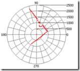
image image

Fig 2. Hokuyo URG-04LX and resulting “map” of surroundings

Waypoint Detection:

Object detection and tracking is usually done with a vision system in robotics applications. Because machine vision is highly dependent on ambient lighting conditions, there are also many possible algorithms that can be applied to object tracking. One method of object tracking is through the use of color. If the color of an object has high contrast with its surroundings, then robots can use cameras to recognize this unique color and isolate its relative position using some further vision processing. Robots can also use geometry to match an object, or even a combination of both. The markers for the waypoints will be brightly colored objects, so your robots can also use geometry to match, or even a combination of both geometry and color. LabVIEW also has example programs to directly interface with the AXIS 206 IP Camera.

image image

Fig 3. AXIS 206 Camera and sample object tracking algorithm screenshot

Suggested Project Timeline

Week 1: Establish connection with CompactRIO and motors.

Week 2: Connect and test Hokuyo LIDAR Sensor.

Week 3: Connect and test AXIS 206 Camera. Test vision algorithm.

Week 4: Fine-tuning navigation algorithm.

Week 5: Final debugging, field trials.

Reminders:

l Always back up your programs!

l Before you start programming, always draw out a flowchart for your logic.

l Be careful of short circuits and live wires. Double check all wiring before powering on!

l When you’re not sure about what a VI in LabVIEW does, remember to use the online help and Example Finder.

l Start early! Leave plenty of buffer time for experimentation.

Be safe, be smart, and have fun.

John Wu

National Instruments Taiwan

wei-han.wu@ni.com

Link to Word document

2009年6月1日 星期一

台大也愛上了 CompactRIO

前一陣子我有機會在台大為羅仁權羅老師介紹 NI 的 LabVIEW 以及 CompactRIO 嵌入式控制平臺,看起來他還蠻滿意的! 現在我們正在規劃一個用 CompactRIO 做機器人的期末專案,希望能夠讓學生們能夠快速學習 CompactRIO 以及利用它的好處。More details to come ...

羅老師可是在台灣數一數二在做機器人研究的學者哦! 各位可以看一下有關於他的研究背景,他還有自己的維基百科哦:

http://www.ee.ntu.edu.tw/profile?id=758

http://zh.wikipedia.org/wiki/%E7%BE%85%E4%BB%81%E6%AC%8A